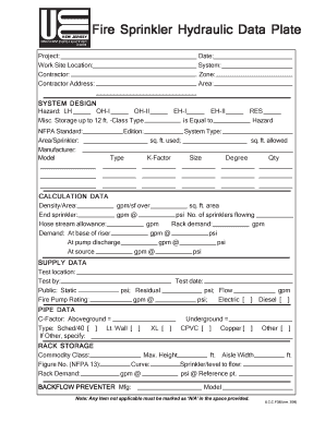
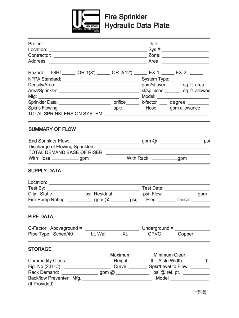
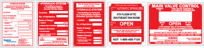
Fire Sprinkler Hydraulic Data Plate

Hydraulic Calc Signs Id Signs Decals Tags Fire Sprinkler Argco Com

Sign Alum 8 1 2 X 11 Hydraulic Data Plate Fire Sprinkler Argco Com
Have I Been Wrong All These Years Filling Out Hydraulic Calculation Placards Nfpa Fire Code Issues Eng Tips
Fillable Online Bridgewaternj Fire Sprinkler Hydraulic Data Plate State Nj Us Bridgewaternj Fax Email Print Pdffiller

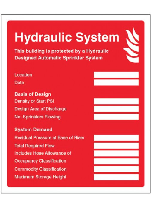
Hydraulic System Sprinkler Sign Seton

Hydraulic System Sign This Building Is Protected By A Hydraulically Designed Sprinkler System Spr 16

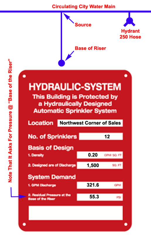
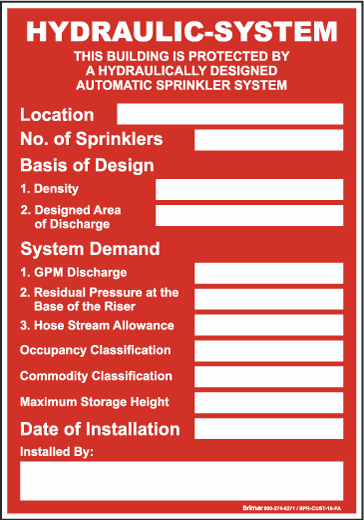
The requirement every hydraulically calculated system is required to have a hydraulic design information sign more commonly known as the hydraulic data plate or placard.
Fire sprinkler hydraulic data plate.
Hydraulic Data Plate Sprinkler Fillable Fill Online Printable Fillable Blank Pdffiller
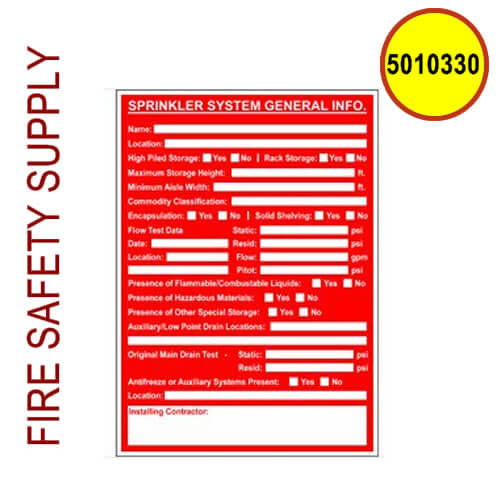
5010330 Sign Alum 5 X 7 Sprinkler System General Information

Hydraulic Design System Sign Spr 17 By Safetysign Com

Complete Guide To Fire Sprinkler Signs And System Marking
Standpipe System Sign 25756 By Safetysign Com
Custom Hydraulic System Location Sign Spr Cust 16 By Safetysign Com

Here Is Your Sign Sprinkler Age

Id Signs Decals Tags Fire Sprinkler Argco Com
Fdny Sign Hydraulic System Sign Automatic Sprinkler Aluminum Hpd Signs The Official Store
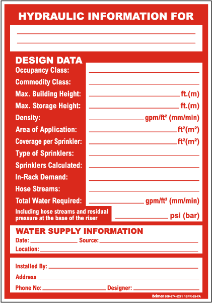
Hydraulic Information Design Data Sign Spr 25 Sprinkler System Signs By Safetysign Com

5010241 Sign Alum 8 1 2 X 11 Hydraulic Data Plate Fire Safety Supply
Hydraulic Sprinkler System Id Plate Sign Safety Signs
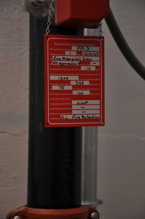
Eno Memorial Hall Simsbury Ct A L Fire Protection
Does Your Fire Sprinkler System Have All The Required Signs
Https Www Columbus Gov Workarea Downloadasset Aspx Id 45974
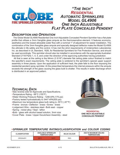
A 10 Gl4906 Globe Fire Sprinklers
Https Www Townofbrighton Org Documentcenter View 4252 Fire Protection System Signage

Sprinkler Identification Signs Fire Protection
Https Encrypted Tbn0 Gstatic Com Images Q Tbn 3aand9gcq4i2abn6nridawkf6z9dzgs2duvf5wizkxqvx7luremmps1i5a Usqp Cau
Https Www Colliertownship Net Documentcenter View 90 Fire Sprinkler System Plan Review Pdf
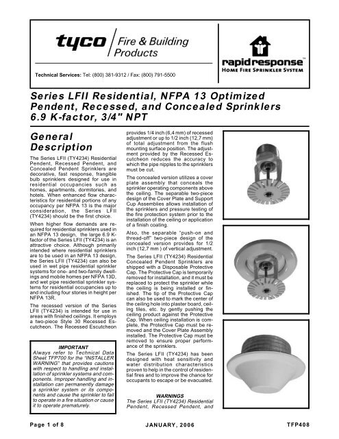
General Description Series Lfii Residential Nfpa 13 Optimized
Https Www Nfpa Org Assets Files Aboutthecodes 13 13 A2018 Aut Ssd Srreport Pdf
Http Www Cscos Com Wp Content Uploads Ny1850 Acceptance Testing Of Sprinkler Systems Pdf

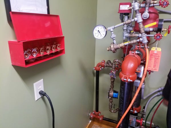
What Is A Fire Riser Room Ifc And Nfpa Codes Standards
Source : pinterest.com
